Municipal > Water > Air And Pressure Control Valves > ARI Air Valves
Published: Thu, Jan 14, 2021
Contributor: Glenn Votkin | Profile | Articles
Recently, a long term client told me they were considering using a competitor’s valve to replace an old valve on an existing water line. Naturally, I was curious and asked them to share the reasons behind their decision. My client indicated that a competitor provided a “cross-referenced” valve and that it was available at half the price of our valve. Like most people, this raised a red flag – could I have misunderstood the application that badly?
As I began to review the technical specifications with the client, it become apparent that we were definitely not having an “apples to apples” conversation. While the two valves shared some dimensional similarities, significant differences existed with respect to performance values. Whether this distinction was deliberately withheld – a wolf in sheep’s clothing – or simply borne out of ignorance doesn’t matter. It would have exposed both my client and the end user to all kinds of problems that come from installing improperly sized valves on a water or a sewer line.I’ll circle back to the specifics of my conversation with my client further down. Before I do, I believe it’s important to understand some of the basic, and not so basic data points that go into this exercise.
Selecting the right air valve can be done the old fashioned way – math calculations. We are fortunate enough to use sophisticated software designed to eliminate a lot of time and potential for human errors. Here’s a link from a previous post that goes into detail about the ARIavCad software.
As part of the data point collecting process, we need to understand the following:
Question #1
Do you have any information on the current valve – make, model #? Are you able to find any information on the type of valve and its performance rating? Here’s the tricky part – even if you do, how do you know it was sized correctly when it was originally installed? The only way to be sure is to cross-reference the performance of the valve and its relationship to flow charts – more on that later.
Question #2
What is the application: sewer or water? What type of air valve is it: single, dual (combo), vacuum breaker?
Does the valve fall under some basic rule of thumbs? For example, in a pump station prior to the check valve, it must always be a combination valve. The same is true if the valve is placed at a pipeline peak. If it’s in an horizontal straightaway you will likely find a single (air release) valve and conversely, if it’s at the inflection point of a slope increase, you’re likely looking at single (air in/vacuum) valve.
Question #3
What is operating pressure of the pipeline?
Sounds basic, and it’s very important to confirm that manufacturer’s technical data sheet clearly identifies the valve will meet the pipeline’s operating pressure requirements.
Question #4
What is flow rate for the pipeline?
It’s important to differentiate that there are effectively two different “flow rates” in play. The first, and what we need to know from our clients, is the flow rate of the water or effluent. This is typically expressed as litres per second (l/s) or gallons per minute (gpm).
The second flow rate refers to a valve’s capacity of air flow and is typically expressed in cubic feet per minute (cfm) or cubic metres per hour (m³/hr).
It is here – the valve’s air flow capacity – if not properly sized, poses the greatest potential risk to a pipeline. For example, in practical terms, if the air pressure within the pipe exceeds the valve’s capacity to exhaust the air, this will cause the valve to prematurely slam shut. This “air slam” phenomenon can produce a shock wave (water hammer) that can bounce back and forth over kilometers of pipeline. Conversely, in a vacuum condition, if a valve cannot allow enough air into the pipe quickly enough, at best, contaminants can enter the pipe through any compromised connection point (undesirable with potable water lines) and at worst, result in full pipe collapse.
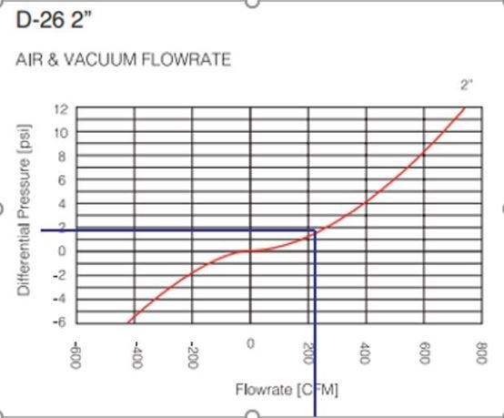
Now that we understand the criticality of the relationship between pipeline flow and a valve’s air flow capacity (pressure and vacuum), we need to know where to find it. Simply put, any valve manufacturer should have air flow charts prominently displayed and available in their technical specifications sheets.
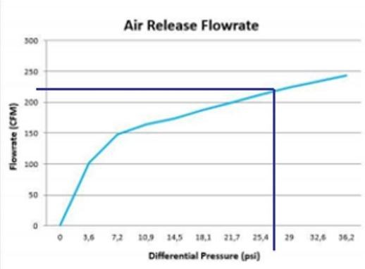
SIDE BAR: Pressure differential rates – which is a measurement of how long a valve will remain “open” when releasing air from a pipeline is another important metric and functional requirement of an optimally performing air valve.
Getting back to the charts, more specifically, they should corelate and easily illustrate the air flow rate and pressure differential values at varying levels of pipeline flow rates. If this information is not included or incomplete, consider it a red flag.
Example #1: Sewer Pipeline, 300mm in Diameter, 150 psi operating pressure and 100 l/s Flow Rate and Application is High Point in System
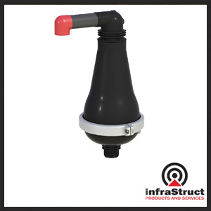
ARI D26 50mm Combination Sewer Air Valve, rated 250 psi operating pressure.
Pipeline Flow @ 100 l/s coverts to 212 CFM.
Example #2, as a comparison, a competitors valve that shares some dimensional similarities.
50mm Combination Sewer Air Valve, rated 250 psi operating pressure.
This information is the absolute minimum amount of data required to properly size air valves. Other factors to consider during the review process are the age of the pipe, any post installation modifications to the pipeline, updated engineering practices and guidelines (i.e., burst analysis values of yesteryear wouldn’t meet today’s minimum accepted values), etc.
Remember my client at the beginning of my story – the one that wanted to install a valve for half price? Turns out that after they applied the calculations discussed above, my client realized that the lower cost valve would have provide about a 6% protection factor, a far cry less than the industry standard of 33% protection factor.
Valves represent a fraction of the cost of the entire pipeline installation and yet the cost of cutting corners is astronomically higher that any potential “savings” and, I hope you will agree that it just isn’t worth it!
Head Office/Products
11571-149 Street
Edmonton, AB
T5M 1W9
780-454-2006
Municipal Services Division
11570 Kingston Street
Maple Ridge, BC
V2X 9J8
604-424-9999

Head Office/Products
11571-149 Street
Edmonton, AB
T5M 1W9
780-454-2006
Municipal Services Division
11570 Kingston Street
Maple Ridge, BC
V2X 9J8
604-424-9999